
Blinking an LED
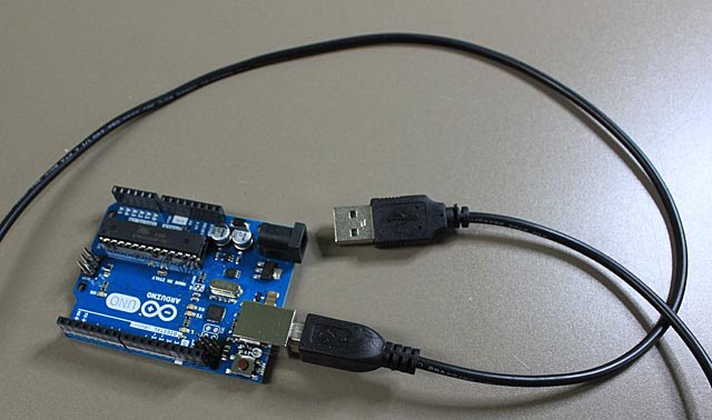
You are going to make one of the LEDs blink on and off. Start by connecting the USB cable to the Arduino's USB socket. Make sure the shapes match.
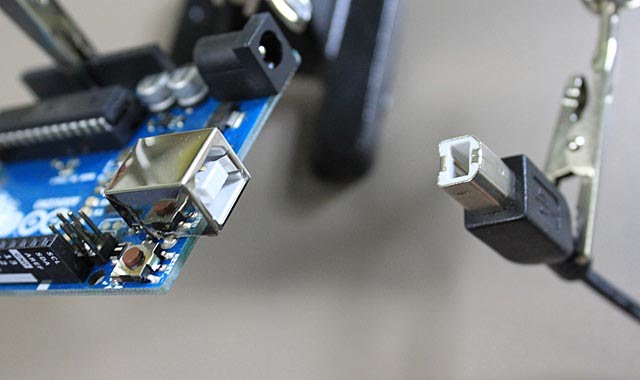
Leave the other end unconnected for now.
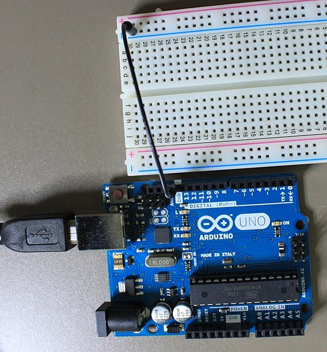
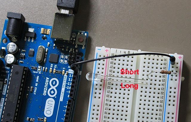
Now get the breadboard and a short black wire. Connect the black wire from the GND socket on the Digital side of the Arduino PCB to one of the - columns (close to a long blue line) on the breadboard.
Now connect one of the resistors from the same - column to another place on the breadboard. I have chosen 25c.
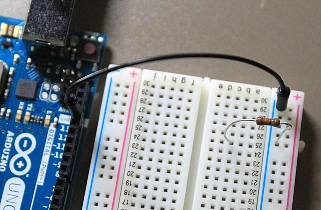
Get one of the LEDs and check which wires are long and short. You should put the SHORT LED wire into the same row as the resistor and the LONG wire into the next row beside it.
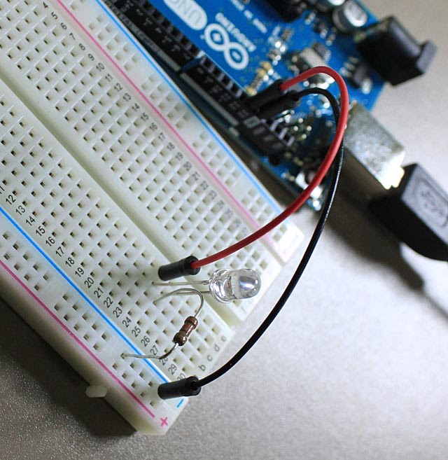
Get a short red wire and connect it to digital output socket 13, right beside the GND socket on the Arduino PCB. Connect the other end of the red wire to the same row as the LONG wire of the LED. Your circuit is complete! The Arduino will send power via port 13 to the LED, and it will flow through the LED (turning it on), then through the resistor (reducing the current) and back to the Arduino's ground port.
But the Arduino needs a power source and some control. It's time to plug the other end of the USB cable into the computer. The computer should already be turned on.

You may see a message like this:
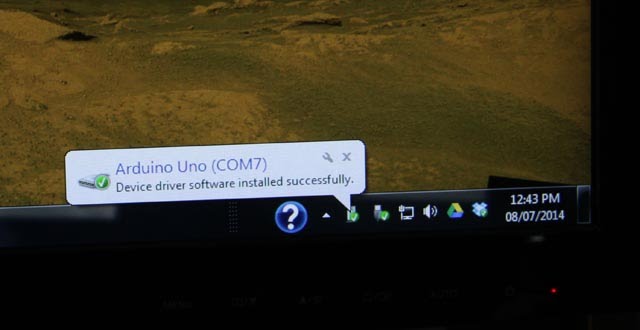
Take note of what COM number the device driver is using. * If you do NOT get the green check mark but a red X instead, then you have to manually install the device driver software. Get help, and/or see this webpage for more instructions (for Windows computers): http://arduino.cc/en/Guide/Windows The Arduino PCB will have a couple of LEDs on it: one steady (power is on) and the other flashing.
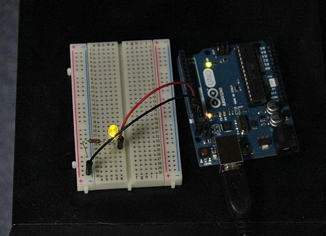
You should note that port 13 is special: it is the only output that is connected to an LED that is built onto the Arduino PCB. This makes port 13 a useful one for testing new sketches and circuits.
Now start up the Arduino IDE (Integrated Development Environment ) on the computer.

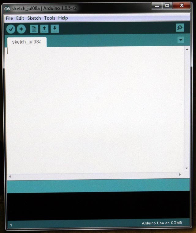
The Arduino automatically starts with a blank sketch with the current month and day as its name. Notice also the COM number at the bottom of the screen. If the number does not match the number that came up when you plugged in the USB cable, then you'll have to change it using the "Tools" menu.
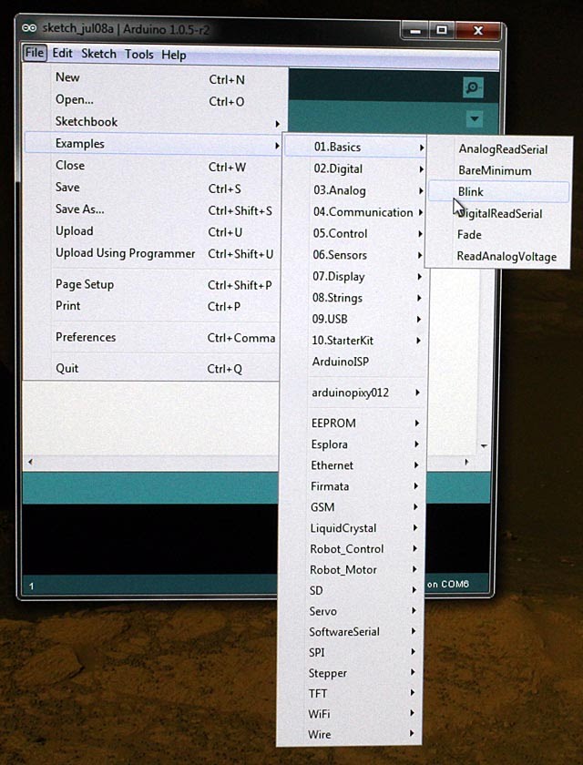
We are going to use a simple sketch called "Blink". You'll have to open it in the IDE now, and then we're going to make some changes to this sketch.
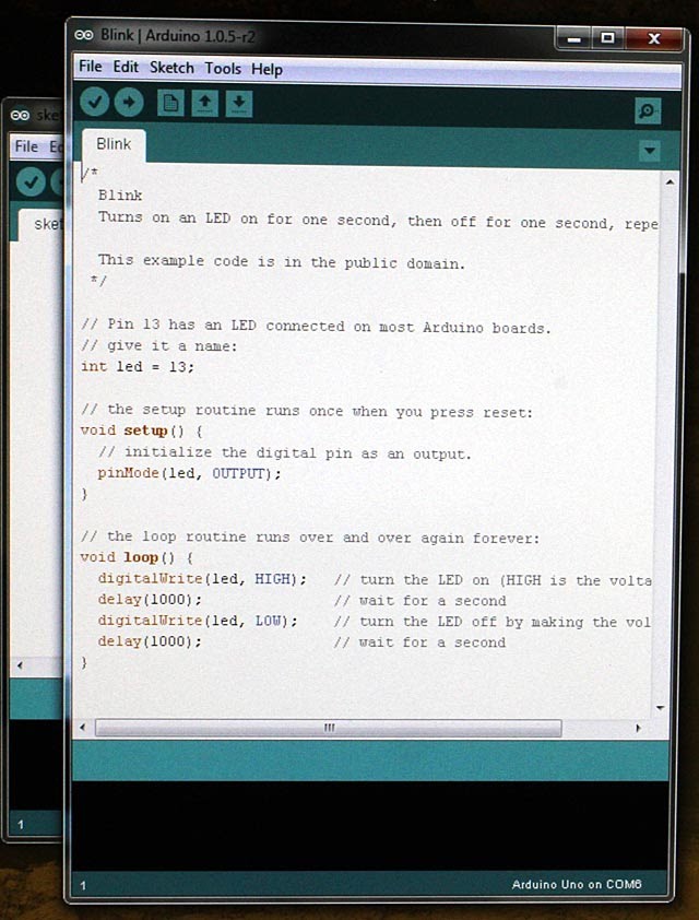
You can see the three main parts of all Arduino sketches:
- creating variables (declarations)
- setup
- loop
In the declarations area, we create a variable "led" that we will use to identify which output socket we want to use - in this example, we used 13. In the setup function, we tell the Arduino that "pin" 13 should be used as an output. The loop function follows the instructions repeatedly and very quickly. If we just had the instructions to turn the LED on and off, it would blink so rapidly that we wouldn't be able to see it. So we also have to include delays to give time for our eyes to notice that the LED is on and then off. The delays are in milliseconds, and 1000 milliseconds is equal to 1 second. Notice that every time we want to tell the Arduino to do something with pin 13, we use the variable led that has the value of 13. This makes it easy to change the code if we move the wire connector to a different pin.
Try changing the delay times to different values. After each change, click on the arrow inside the circle near the upper left corner of the window to upload the new code to the Arduino. After a minute or so, the Arduino should change the way it blinks the LED. If you make the delays very short (about 10 milliseconds or less), you won't be able to notice the blinking, but the LED will appear to be dimmer than usual. If the delay after turning the LED off is longer than the delay after turning the LED on, then the LED will be very dim. If you reverse the delay lengths, then the LED will be brighter.
Try changing the wire connecting the LED to the Arduino to socket (pin) 12 instead of 13. It won't blink until you also change the code by changing the value of the led variable. Try adding more LEDs to your breadboard and more wires connecting their longer wires (positive) to other digital output pins on the Arduino. Make sure all the shorter LED wires are connected to the resistor. Then change the sketch code to make all the LEDs blink in different patterns. Are you beginning to see how holiday decorations are made?