
Getting Started with Arduino
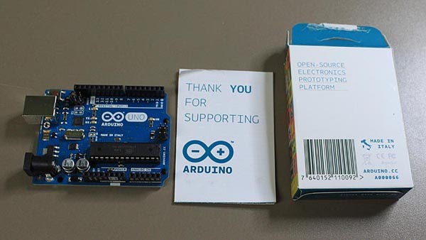
(Link to a similar video tutorial.)Open your Arduino electronics kit, and find the following items:
Handling just the edges of the board, take a closer look at the Arduino microcontroller.
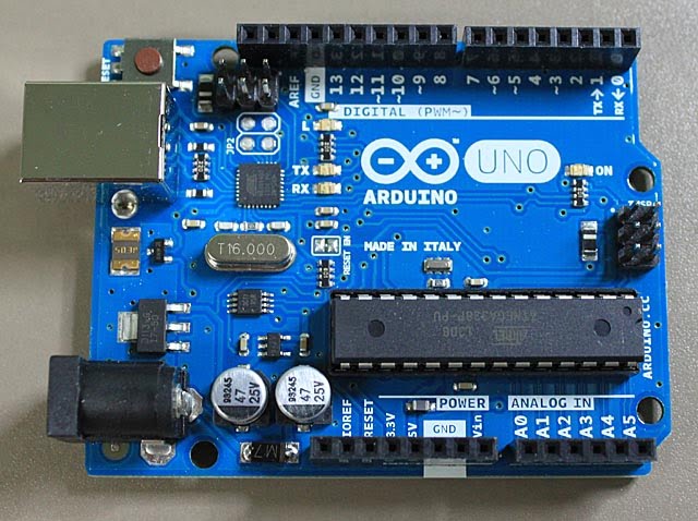
This Printed Circuit Board (PCB) holds a variety of components that work together to
- accept electrical input signals from devices in the real world,
- process them in a microcomputer,
- output electrical signals that can control devices in the real world.
The long, black, rectangular component contains the microcomputer chip. Its official code name is ATmega328. If you look closely, you can see that name on its label. This is the "brain" of the Arduino.
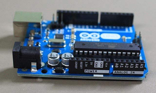
Along one side of the Arduino PCB are the power input and analog input sockets. If you are using the Arduino by itself, without attaching it to another computer, you can attach a battery with the positive side to Vin and the negative side to GND. NEVER attach an external power source (battery) to the other sockets. Later, we will be attaching various sensors to the analog input sockets A0 to A5.
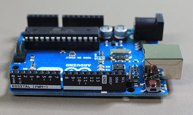
Along the other side of the Arduino PCB are the digital input and output sockets. This is where we will be connecting switches (for digital inputs) and various output devices (like Light Emitting Diodes (LEDs). The digital sockets are labelled 0 to 13. The first two (0 and 1) are used for communication with another computer and are labelled RX (receive) and TX (transmit). You should avoid using these for other purposes.
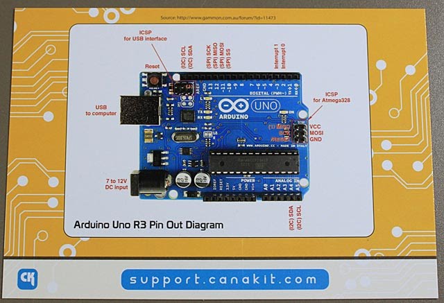
Your kit also contains this labelled diagram of the Arduino. The two other parts you need to know about are the shiny metal box containing the USB (Universal Serial Bus) connector and the black plastic cylinder containing the DC (direct current) power input connector. The USB connector is the main method of connecting the Arduino to another computer where programs (sketches) will be created and uploaded to the Arduino. The USB connector also provides power to the Arduino. The DC power input connector allows you to power the Arduino (without using a computer) from a wall jack (similar to a cell phone recharger.)
Now look for some other items in your kit.
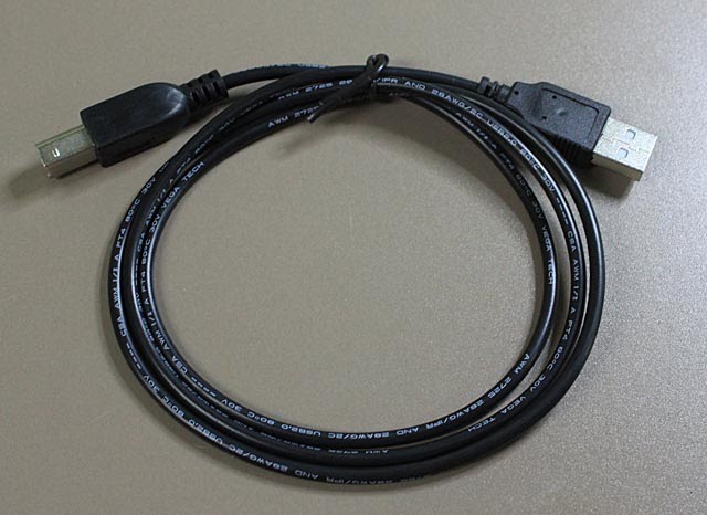
This is the USB cable that will connect the Arduino to another computer.
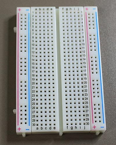
This is a "breadboard" where we can temporarily connect components together with wires. Hidden from view, the sockets are connected together in sets. The four columns labelled + and - are connected along those columns. These are usually used to supply power + and ground - to the other components. The thirty rows have a, b, c, d, e connected together and f, g, h, i, j connected together.
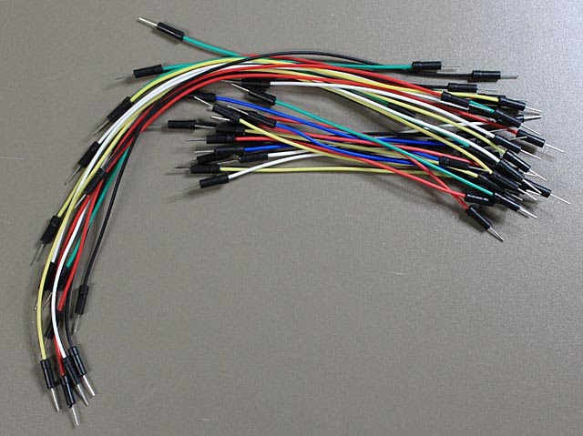
These are the wires we will use to connect components together. The ends have special reinforced tips for putting into the sockets on the Arduino PCB and the breadboard. The coloured insulation on the wires helps us keep track of the connections. Red is usually used for + power, black is usually used for - ground.
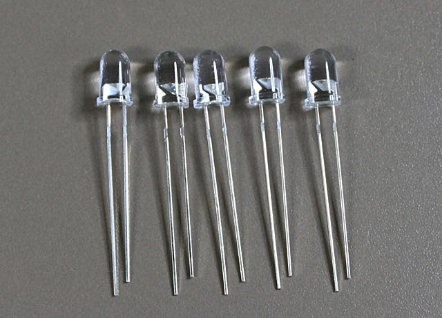
These are Light Emitting Diodes (LEDs). They actually shine with several different colours, but we won't know which until we turn them on. The longer wire must be connected to the + power and the shorter wire must be connected to the - ground. They won't work with the opposite connections. LEDs should also be connected with a resistor in the circuit to prevent them from getting too much current.
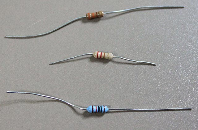
These are resistors. They reduce the amount of current flowing in a circuit. the coloured stripes are a code that tells us how many Ohms of resistance they have.